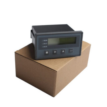
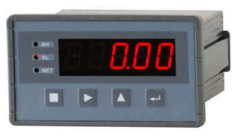
Weighing / force measuring controller BST106-B60S [L]
-
Model:BST106-B60S [L]
-
Мanufacturer:Supmeter
BST106-B60S [L] Weighing/force measuring controller
Weighing/force display, peak detection/hold, automatic checkweighing, fixed DO output and analog to analog/digital transmission
Implementation of standards
- PRC GB/T 7724-2008 National standard of electronic scale.
- PRC JJG 649-2016 National rules for the verification of digital weight indicators.
- OMIL R76-1: 2006 International guideline for non-automatic weighing instruments.
- Accuracy class:○Ⅲ.
- Number of test scale intervals: n=3000.
Display
- 5 red LED digital tubes to display English characters and numbers.
- Weight display range: -9999~+99999.
- Scale capacity: parameter range 1~99,999.
- Scale division: optional 1, 2, 5, 10, 20, 50, 100, 200, 500.
- Screen resolution: 1/50,000.
- Decimal point position: optional 0, 0.0, 0.00, 0.000, 0.0000.
- Display refresh time: Setting range 0.01-1.00 s.
Keyboard
- 4-keyboard for working in menu and shortcut mode.
Weighing signal interface
- Excitation voltage/max. Current 1: 5 In post. current/120 mA for strain gauges 8–350 Ω.
- Excitation voltage/max. Current 2: DC12V/100mA for weight sensor.
- Additional mV, V and mA weighing input for connection of “mV output load cell”, “voltage output load cell” and “current output load cell”.
- 【mV】 Input signal range: 0~19.5mV [Strain sensor output sensitivity: 1.0~3.5mV/V].
- 【V】 Input signal range: 0~2.5V, 0~5V, 0~10V.
- 【mA】 Input signal range: 0~20mA.
- 24-bit Σ-ΔADC with 1/1,000,000 internal resolution.
- Additional sampling rate: 10 Hz, 40 Hz, 640 Hz, 1280 Hz.
- Special anti-vibration digital filtering algorithm for accurate weighing, stable display and fast response.
- Zero drift: ±0.1 µV/℃ RTI (relative to input).
- Gain drift: ±5ppm/℃.
- Non-linearity: 0.005% of full scale.
Switching signal interface
- 1 normally open switch input [DI].
- 2 relay outputs with normally open and normally closed contacts [DO].
- Contact power of the relay switch: AC250V/DC24V, 1A.
Analog signal interface
- 1 configurable analog output [AO: 4~20mA / 0~20mA / 0~5V / 0~10V / …].
- Non-linearity: 0.05% of full scale.
Digital communication interface
- COM1: RS232.
- COM2: RS485.
- Connectivity: main IPC/PLC and remote LED display.
Operating characteristics
- Operating voltage 1: 24 V DC ± 20%.
- Operating voltage 2: 85~264 V AC, 50/60 Hz.
- Max. Power: 5 W.
- Overall dimensions: 107×60×100 mm [W×H×D].
- Panel cutout size: 95×48 mm [W×H].
- Operating temperature: from -25℃ to +45℃.
- Storage temperature: from -30℃ to +60℃.
- Relative humidity: max. 85% relative humidity.
- Protection level of the front panel: IP65.
- Weight: approx. Weight: 0.3 kg.
User interface diagram

Working with the keyboard
If there is no keyboard operation for one minute and it is not in the processes of “System Calibration F2” and “Factory Reset F6”, the controller will automatically return to the “Main Display Interface”.
|
Working with the menu |
|
| Key |
Description |
| 【■】 | Enter the main menu / exit. |
| 【8】 | Log in / Save / Clear alarm. |
| 【►】 | The cursor moves to the right.
Show previous version. |
| 【▲】 | Display the next interface or option.
Digital input: +1 (cycle 0~9). |
|
Fast work mode A Parameter [904] = ‘0. dE’ [Default setting] |
|
| 【■】* | Ø Locking with a key.
Ø Unlocking with a key. |
| 【►】
【SET】 |
Adjusting the setting parameters. |
| 【►】*
【ZERO】 【→0←】 |
Ø [-ZEro]: Zero calibration with power failure protection and tare weight reset.
Ø [≡ZEro]: Manual zero setting without power-off protection and without tare weight reset. Ø The controller will switch to gross weight display. |
| 【▲】*
【TARE】 【→T←】 |
Ø [≡tArE]: Manual taring without power-off protection.
Ø [-PStr]: Pre-tare weight with power-off protection. Ø [-rStr]: clear tare weight with power off protection. Ø The controller will switch to net weight display. |
| 【8】
【G/N】 |
Gross weight / net weight / peak net weight display switch. |
| 【8】*
【CLS】 |
Ø [-CLS-] : Clear Screen [Clear Peak Hold Value]. |
*: Hold the key for 2 seconds.
|
Quick mode parameter [904] = ‘1. Oh |
|
| 【■】* | Ø Key lock (except【ZERO】and【TARE】key).
Ø Unlocking with a key. |
| 【►】
【ZERO】 【→0←】 |
Ø Zero calibration with power failure protection and tare weight reset.
Ø The controller will switch to gross weight display. |
| 【▲】
【TARE】 【→T←】 |
Ø Manual tare with power failure protection.
Ø The controller will switch to net weight display. |
| 【8】
【G/N】 |
Gross weight / net weight / peak net weight display switch. |
| 【8】*
【CLS】 |
Ø [-CLS-] : Clear Screen [Clear Peak Hold Value]. |
*: Hold the key for 2 seconds.
Status indication
| LED |
Description |
Note |
| [AH] | Upper limit alarm. | See parameters [200]~[203]. |
| [AL] | Low limit alarm. | |
| [NET] | Ø OFF: Display gross weight.
Ø ON: Net weight display Ø Fast flashing: In the process of determining the peak value. Ø Slow flashing: Peak value display detection result. |
Initial display after power on:
Ø [203] = 0: Net weight. Ø [203] = 1: Gross weight. Ø [203]=2: Peak net mass value. |
Signal signs
| Signal |
Reason |
Decision |
| Err0 | Weighing signal type error. | Turn on the power again, making sure that the setting of parameter [111] “Weighing signal type” and the position of the DIP1/DIP2 switch match the actual weighing signal input. |
| Err1 | RAM failure. | Replace the RAM chip. |
| Err2.1 Err2.2 | EEPROM failure. | Replace the EEPROM chip.
|
| Err3 | Unutilized. | |
| Err4 | ADC failure. | Replace the ADC module. |
| oV-Ad | Exceeding the ADC range. | The weighing signal exceeds the analog-to-digital conversion range.
1. Check if the strain gauge is connected. 2. Check whether the strain gauge capacity is too small. 3. Check if the loading weight is too heavy. |
| oL | Load alarm. | Total weight > (Weight capacity + 9 × weight distribution).
1. Check if the strain gauge is connected. 2. Check whether the strain gauge capacity is too small. 3. Check if the loading weight is too heavy. |
| oV-tr | Does not meet the condition of manual packaging. | When the gross weight is in a negative display, overload alarm, or dynamic change state, “Manual Tare” will be invalid. |
| oV-nZ | Exceeding “manual/automatic zero limit”. | See parameter [123] “Manual/automatic zero limit”. |
| tXX.XX | Preheating time countdown [min.sec]. | See parameter [128] “Zero at power-on”, [129] “Zero time at power-on” and [130] “Zero limit at power-on”. Wait for the preheat time to expire or press any key to exit. |
| oV-Zr | Exceeding the “zero limit at power-on”. |
Installation and connection
Установка

Terminal

DV24V
|
Select the weighing signal by setting the DIP1/DIP2 switch and parameter [111] “Weighing signal type”. |
|||||
| Weighing signal | 0~19.5mV | 0~20mA | 0~2.5V | 0~5V | 0~10V |
| DIP1[on rear panel] | Left[mV] | Case[mA] | Middle【V】 | Middle【V】 | Middle【V】 |
| DIP2 Internal switch | Left[NC] | Left[NC] | Left[NC] | Middle[5V] | Case[10V] |
| Setting parameter [111] | ‘19.5EV’ | ’20EA’ | ‘2.5V’ | ‘5V’ | ’10V’ |
| Default setting | √ | ||||
When the value [111] “Value signal type” is set, the position of the DIP1/DIP2 jumper is responsible for the actual input signal signal.
For the signal [V]/[ma], the “SIG-” and “EXC-” terminals are short-circuited; Otherwise, the sampling signal will be unstable.
| No. | Pin | Description | |||||
| LOADCELL |
【mV】Weighing Signal |
[V]Weighing Signal |
【mA】Weighing Signal |
||||
| 1 | SIG+ | Weighing Signal Input +. | Weighing Signal Input +. | Weighing Signal Input +. | |||
| 2 | SIG- | Weighing Signal Input -. | Weighing Signal Input -. [‘SIG-‘ and ‘EXC-‘ should be shorted] | Weighing Signal Input -. [‘SIG-‘ and ‘EXC-‘ should be shorted] | |||
| 3 | EXC- | Excitation Voltage -. | Excitation Voltage -. | Excitation Voltage -. | |||
| 4 | EXC+ | Excitation Voltage+. [DC5V] | Excitation Voltage+. [DC12V] | Excitation Voltage+. [DC12V] | |||
| COM1 | RS232 Digital Communication Port | ||||||
| 5 | TXD | Transmit Data. | |||||
| 6 | RXD | Receive Data. | |||||
| 7 | GND | Signal Ground / Shield Ground. | |||||
| 8 | DI1 | Switch Signal Input 1. | |||||
| [DC] POWER | DC24V[±20%] Power Input Port | [AC] POWER | AC85~264V Power Input Port | ||||
| 9 | DC- | DC Input -. | 9 | N | Null Wire. | ||
| 10 | DC+ | DC Input +. | 10 | L | Live Wire. | ||
| The metal shell should be grounded directly. To strengthen the controller between driving devices, DC24V, the strength of the controller is not shared by the DO. | |||||||
 all products

-
Manufacturer:Constant Wes
-
Equipment:Software "Car scales"


 Main office:
  Phones:
  Mail
Mail 


